
A film COF number is hard to use when its contacting surfaces are unspecified. Record which film face touches which surface, separate static from kinetic results and connect the laboratory report to a controlled trial on the actual packaging machine.
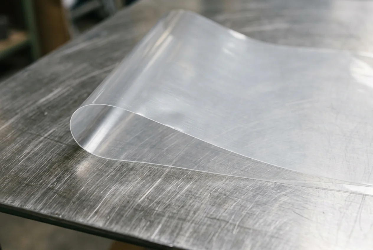
Coefficient of friction describes a contact pair, not a complete prediction of film machinability. Use the sample record below to keep face, direction, lot and test method with each result. Then compare line symptoms against a retained reference material under documented settings. This guide gives no universal acceptable COF band or standard test settings.
Identify the contact pair
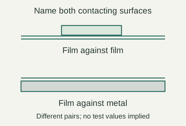
Film-on-film and film-on-metal address different interfaces. A result measured on one pair should not be silently applied to the other. Shimadzu’s published measurement overview explicitly discusses both film-to-film contact and contact with another material, and distinguishes static and dynamic friction measurements.
Static friction concerns the onset of sliding; kinetic friction concerns sliding after motion begins. Ask the laboratory which result it reports and how it summarizes it. A single unlabelled value cannot answer both questions.
| Sample field | Enter before testing | Reason |
|---|---|---|
| Film identity | Structure, supplier, lot and roll reference | Makes the sample traceable |
| Contacting surfaces | Inside/outside face and opposing material | Defines the actual pair |
| Direction | Machine direction or transverse direction as supplied | Keeps orientation consistent |
| Reported quantity | Static or kinetic/dynamic, as the method defines | Prevents unlike results being compared |
| Test conditions | Laboratory method, revision and reported conditions | Preserves the basis of the result |
| Sample history | Storage, conditioning and handling record | Helps explain a changed sample state |
Use the laboratory’s current method and the machine supplier’s material requirements. We have not reproduced a normative test procedure here, so the table is not a substitute for a standard or an instrument manual.
Connect the sample to its roll
Retain a clearly identified reference and preserve the face orientation. A loose offcut can lose its relationship to the web direction and the roll that ran well. Mark that information in the accompanying record, using a method that does not alter the test area.
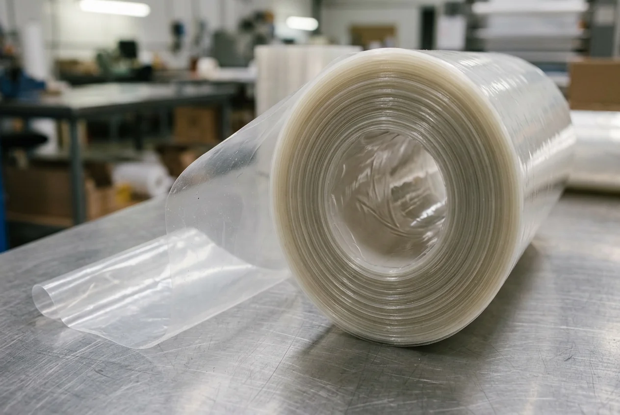
Keep material changes separate from changes in the equipment. If a new roll, different settings and a modified forming set all enter the trial together, a better result cannot identify which change helped. Record unavoidable combined changes and limit the conclusion accordingly.
Observe the web before assigning a cause
ROVEMA’s published discussion links film friction with transport, forming-collar loading and symptoms such as wrinkling or tracking problems. It also discusses power-unwind assistance as one equipment approach. Those relationships justify investigating the interface; they do not prove that friction caused a particular fault.
| Observed symptom | Record first | Competing checks to keep open |
|---|---|---|
| Tracking changes | Roll, edge position and time of change | Web alignment, tension and machine condition |
| Wrinkles near forming | Location and retained sample | Material presentation and forming setup |
| Registration variation | Mark/print reference and affected packs | Sensor/setup checks under the machine procedure |
| Intermittent drag | Where and when it occurs | Contact surface condition and material change |
| Seal defects | Defect location and sample | Product contamination and sealing conditions |
Do not respond to drag by treating the lowest possible COF as the goal. A line needs controllable material handling across its actual interfaces. Have the film and machine suppliers agree what to test and what evidence would support a material or setup change.
Keep the line trial reproducible
Use accepted production as the outcome, with the agreed pack checks alongside the transport observations. Run the retained reference when practical, then the candidate material using a documented comparison plan. Do not present a machine cycling without product as proof of filled-pack performance.
| Trial entry | Reference film | Candidate film |
|---|---|---|
| Roll / lot / face orientation | ___ | ___ |
| Machine and forming-set reference | ___ | ___ |
| Product, dose and pack geometry | ___ | ___ |
| Settings and changes authorized | ___ | ___ |
| Observation window and stops | ___ | ___ |
| Transport symptoms and reject types | ___ | ___ |
| Accepted-pack checks and disposition | ___ | ___ |
Record the decision with its scope: this film, on this configuration, with this product and acceptance rule. If the material route itself is still undecided, use the VFFS and premade-pouch comparison before commissioning a detailed trial.
Methods and sources
Shimadzu’s measurement overview supports the paired-surface and static/dynamic distinction. ROVEMA’s film-friction article, updated 20 August 2024 and available in the local archive, supplies the machine-interface context. The sample and trial tables are editorial proposals. No ASTM or ISO clause, instrument setting or universal threshold is asserted. Sources were retrieved on 16 October 2026. See materials and machinability for the wider decision context.
Source documents read:
- Plastic Film Frictional Coefficient Measurement (retrieved 16 October 2026).
- Film coefficient of friction and VFFS operation (retrieved 16 October 2026).
- How do Vertical Form Fill Seal Machines Work? (retrieved 16 October 2026).